At its core, a VFD is a power conversion device. It takes standard fixed-frequency AC power from the mains and transforms it into a variable-frequency, variable-voltage output to control a motor. This complex conversion happens in three distinct stages: the Rectifier, the DC Bus, and the Inverter.

The rectifier stage converts incoming AC mains power into DC voltage using semiconductor switching devices. This conversion forms the foundation for subsequent frequency synthesis, as DC provides the stable reference needed for precise output control.
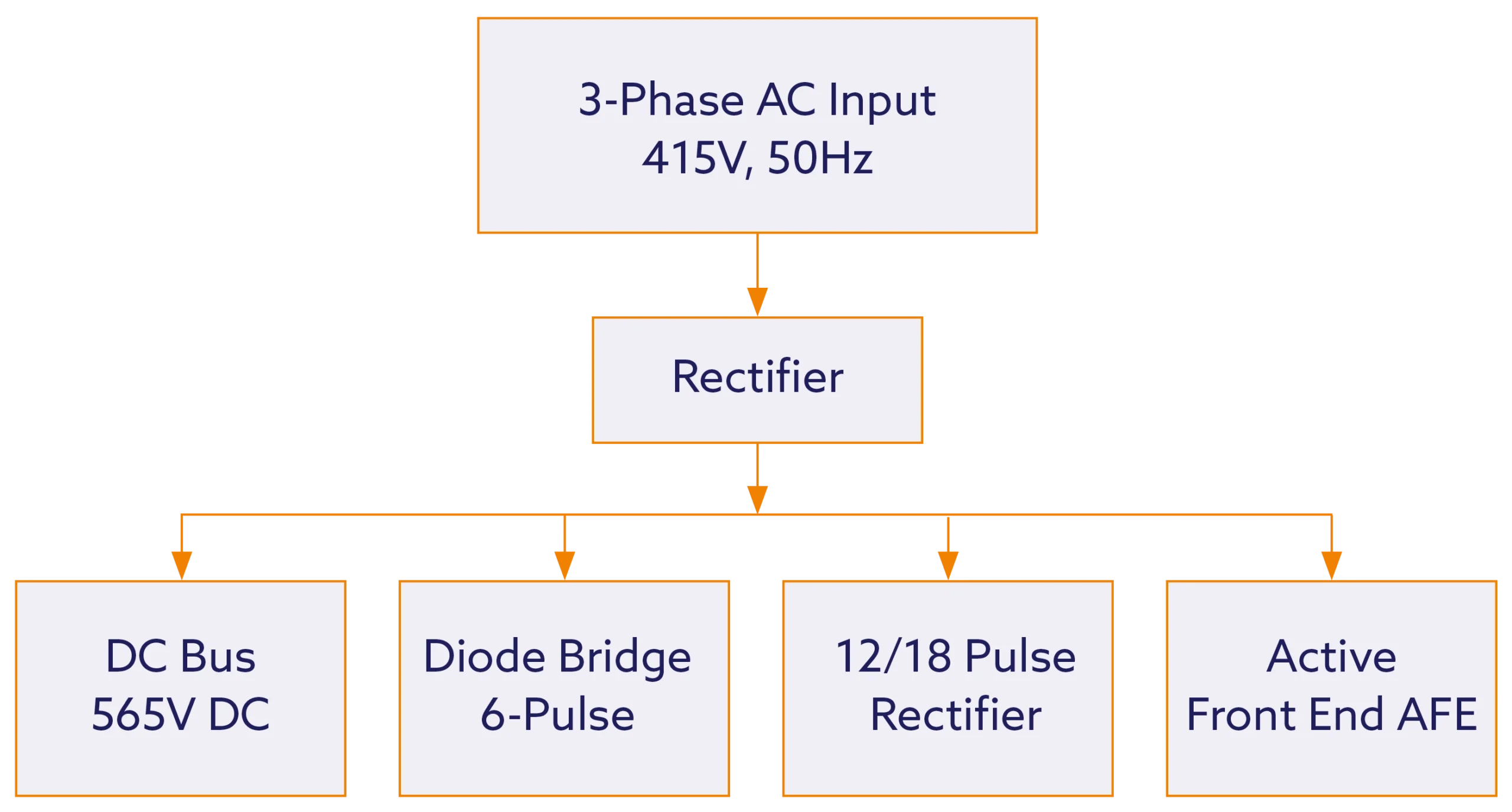

This is the most common and cost-effective topology, found in the vast majority of standard VFDs. It uses six diodes to rectify the three-phase AC supply, creating a raw DC voltage with a noticeable “ripple”. While economical, this design introduces current harmonics back into the supply network, primarily at the 5th, 7th, 11th, and 13th orders.
These more complex designs are employed in high-power applications or where stringent power quality standards must be met. They use multiple 6-pulse rectifier bridges fed by phase-shifting transformers. This arrangement cancels out lower-order harmonics, resulting in significantly lower Total Harmonic Distortion (THD).
An AFE, also called an Active Rectifier, replaces the passive diodes with controllable switching transistors (IGBTs). This technology offers two major advantages:
1. Ultra-Low Harmonics: It actively shapes the input current to be nearly sinusoidal, achieving THD levels below 5% and a power factor near unity.
2. Regenerative Capability: It allows for bi-directional power flow. During motor braking (deceleration), the kinetic energy from the load is converted back into electrical energy and fed back to the AC supply, offering substantial energy savings in applications with frequent start/stop cycles, such as cranes or elevators.
| 6-Pulse Diode | 25-35 | 0.85-0.95 | No | General purpose, cost-sensitive |
|---|---|---|---|---|
| 12-Pulse | 8-15 | 0.90-0.96 | No | Multiple drives, sensitive loads |
| 18-Pulse | 4-8 | 0.92-0.98 | No | Critical power quality applications |
| AFE | <5 | 0.98-1.00 | Yes | High-performance, regenerative loads |
The DC bus section provides energy storage and voltage stabilisation between the rectifier and inverter stages. Proper DC bus design ensures stable operation across varying load conditions whilst minimising voltage ripple that could affect output quality.
Electrolytic capacitors store energy and smooth voltage ripple from the rectifier stage. Capacitor sizing directly impacts:
Many drives incorporate DC bus inductors (DC chokes) to:
For standard 415V three-phase supply:

The inverter stage represents the heart of VFD technology.
The inverter reconstructs AC from the stabilised DC using high-speed semiconductor switches such as:
IGBTs (Insulated Gate Bipolar Transistors) – standard in most industrial drives
MOSFETs – used in lower-voltage, high-frequency applications
SiC (Silicon Carbide) devices – emerging for high-efficiency, high-temperature, and compact designs
These devices are controlled using Pulse Width Modulation (PWM) — a technique that switches the devices thousands of times per second (typically 2–16 kHz) to create a synthetic AC output waveform of variable frequency and voltage.
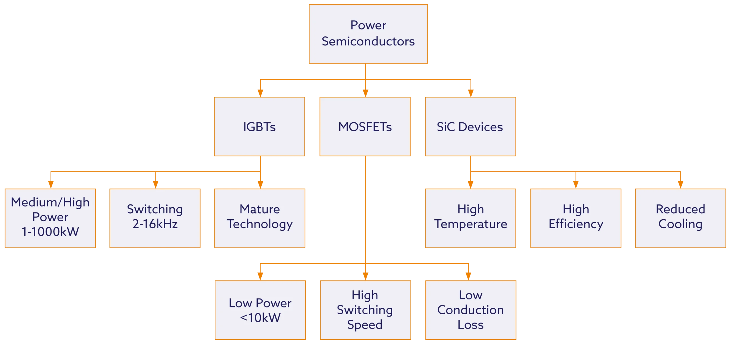
IGBTs dominate medium and high-power VFD applications due to their excellent switching characteristics and robust construction. Modern IGBTs switch at frequencies between 2-16kHz, with higher frequencies providing:
SiC power devices represent the latest advancement in VFD technology, offering:
The inverter generates variable-frequency AC output through PWM switching techniques. The most common approach, sinusoidal PWM (SPWM), compares a low-frequency sinusoidal reference with a high-frequency triangular carrier wave to determine switching instants.
Motor speed control through frequency variation relies on the fundamental relationship between supply frequency and synchronous speed:
This relationship enables precise speed control across the full operating range:
| Motor Poles | 50Hz Speed (RPM) | 25Hz Speed (RPM) | 75Hz Speed (RPM) |
|---|---|---|---|
| 2 | 3,000 | 1,500 | 4,500 |
| 4 | 1,500 | 750 | 2,250 |
| 6 | 1,000 | 500 | 1,500 |
| 8 | 750 | 375 | 1,125 |
To maintain constant motor flux and torque capability, VFDs typically maintain constant voltage-to-frequency ratio. This V/f control ensures:
Above base frequency (typically 50/60Hz), voltage cannot increase proportionally due to DC bus limitations. In this field weakening region:
The three-stage VFD architecture provides the foundation for sophisticated motor control, enabling precise speed regulation, energy efficiency, and enhanced process control across diverse industrial applications.
In part 3 of this series, we will look at the different types of VFD control methods.
VFDs have evolved beyond simple speed control. Today’s drives are smart systems that boost energy efficiency, enable precise automation, and connect seamlessly with modern factory networks.
1. Choose the right drive for your specific application and environment
2. Install it properly following best practices and safety standards
3. Maintain it well with regular checks and smart monitoring technology
We know that buying the right equipment is just the beginning. Our experienced engineers work with you at every step:
Selection: We help you choose the perfect drive for your needs
Installation: Our certified technicians ensure everything is set up correctly
Support: We provide ongoing maintenance and troubleshooting when you need it
Whether you’re building new systems, upgrading old equipment, or looking to cut energy costs, we have the drives and expertise to help. Our team stocks leading VFD brands and has the technical knowledge to make your project successful.
Contact Betech today and let us help you find the right drive solution for better performance, lower costs, and reliable operation.