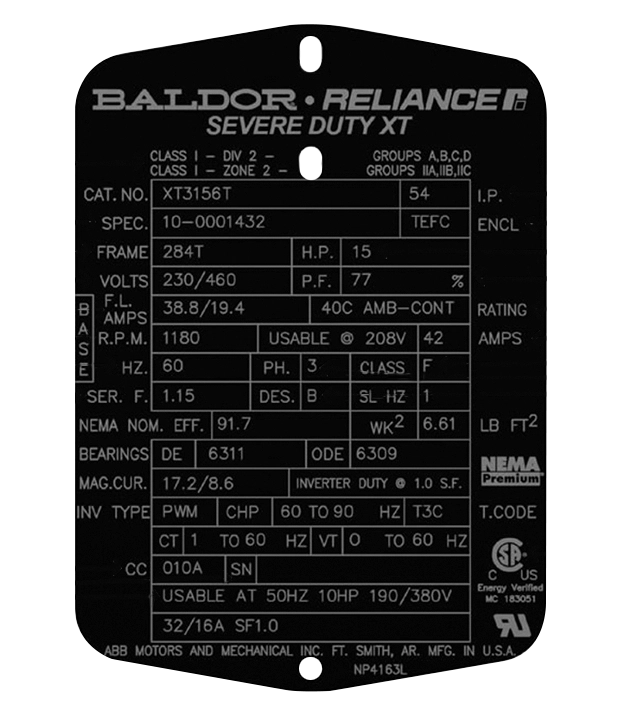
NEMA (National Electrical Manufacturers Association) motor nameplates provide information about the motor’s specifications and operational requirements.
Manufacturer
Hazardous Location Classes and Groups
Frame Size
Rated Voltage (VOLTS)
Rated Full Load Speed (F.L.AMPS))
Rated Full Load Speed (R.P.M.)
Frequency (HZ)
Service Factor (SER.F. or S.F.)
Efficiency (NEMA NOM. EFF.)
Bearings (DE and ODE)
Certified Compliant Number (CC)
Serial Number (SN)
Alternate Ratings or Additional Application Data
Alternate Ratings or Additional Application Data
Rated Horsepower (H.P.)
Power Factor (P.F.)
Ambient Temperature an Time Rating (RATING)
AMPS
Insulation Class
Phase (P.H.)
Design Letter (DES.)
Rotor Inerta
T-Code
Safety and Efficiency Certification Marks
This guide explains the key elements found on a NEMA motor nameplate and how to read them:
Identifies the company that manufactured the motor. This field can vary in format across different manufacturers. As well as the company name, it may include the motor’s model number, electrical design style, or intended purpose.
Critical information for specifying a motor in hazardous environments, where fire or explosion risks exist due to flammable, combustible, or ignitable substances. Locations are categorised into classes and groups based on the autoignition temperature of hazardous materials.
Refer to the table below for detailed classifications.
| Class | Group | Hazardous Material | Autoignition Temp °C | Autoignition Temp °F |
|---|---|---|---|---|
| I | A | Acetylene | 305 | 581 |
| I | A | Butadiene | 420 | 788 |
| I | B | Ethylene Oxide | 570 | 1,058 |
| I | B | Hydrogen | 500 | 932 |
| I | B | Acetaldehyde | 175 | 347 |
| I | B | Cyclopropane | 498 | 928 |
| I | C | Diethyl Ether | 180 | 356 |
| I | C | Ethylene | 450 | 842 |
| I | C | Isoprene | 398 | 743 |
| I | C | Acetone | 465 | 869 |
| I | C | Ammonia | 651 | 1,204 |
| I | C | Benzene | 498 | 928 |
| I | C | Butane | 287 | 550 |
| I | D | Ethane | 472 | 882 |
| I | D | Ethanol | 363 | 685 |
| I | D | Gasoline | 246-280 | 475-536 |
| I | D | Methane | 537 | 999 |
| I | D | Propane | 450 | 842 |
| I | D | Styrene | 490 | 914 |
| II | D | Aluminum | 650 | 1,202 |
| II | D | Bronze | 370 | 698 |
| II | E | Chromium | 580 | 1,078 |
| II | E | Magnesium | 620 | 1,148 |
| II | E | Titanium | 330 | 626 |
| II | E | Zinc | 630 | 1,166 |
| II | F | Coal | 610 | 1,130 |
| II | F | Corn | 400 | 752 |
| II | F | Nylon | 500 | 932 |
| II | G | Polyethylene | 450 | 842 |
| II | G | Sugar | 350 | 662 |
| II | G | Wheat | 480 | 896 |
| II | G | Wheat Flour | 380 | 716 |
Indicates the standardised dimensions of the motor, ensuring consistent mounting and shaft information across different manufacturers. NEMA frame sizes refer only to mounting interfaces and do not directly relate to the motor body diameter.
Specifies the optimal operating voltage for the motor, with a typical tolerance of ±10%. For instance, a 460V motor can operate between 414V and 506V. Note that performance characteristics like power factor, efficiency, torque, and current are based on the rated voltage and frequency. Deviations from the voltage stated on the nameplate will impact motor performance.
This value indicates the current draw of the motor when operating at its rated load and voltage. Motors with a lower full-load amps rating for the same horsepower are considered more efficient.
Indicates the speed at which the motor delivers full load torque at the rated voltage and frequency. The difference between this speed and the synchronous speed is called slip, determined by the motor’s design. Typically, for induction motors, the full load speed is between 96% and 99% of the synchronous speed.
Represents the input power frequency (cycles per second) for optimal motor operation at rated power, voltage, and speed. Motor and power supply frequencies must match. If multiple frequencies are listed that will differ at different input frequencies, corresponding variations in other parameters will also be indicated. 50Hz is most common in the UK and elsewhere, while 60Hz is prevalent in the US.
The service factor specifies the amount of continuous overload the motor can handle without overheating or sustaining damage, under the exact conditions (voltage, frequency, etc.) listed on the nameplate. It provides a safety margin beyond the rated horsepower.
To determine the maximum allowable horsepower, multiply the rated horsepower by the service factor. For example, a 10 HP motor with a 1.15 service factor can operate up to 11.5 HP (10 x 1.15) on a continuous basis without exceeding its temperature rise limits.
It’s important to note that operating a motor above its rated horsepower, even within the service factor allowance, will generate excess heat and potentially reduce the motor’s insulation and bearing life expectancy compared to operating at the exact rated load.
NEMA MG1 9.15.1 clearly states: “An induction motor operated at any service factor greater than 1.0 will have a reduced life expectancy compared to operating at its rated nameplate horsepower.”
The service factor can also help determine if the motor can be operated continuously at altitudes higher than 3,300 feet. At altitudes greater than 3,300 feet, the lower density of air reduces the motor’s cooling ability, causing the temperature of the motor to be higher. This higher temperature is compensated for by reducing the effective service factor to 1.0 on motors nameplated with a 1.15 service factor or greater. However, if the motor is operated outdoors at higher altitudes, it’s sometimes possible to use full horsepower and full-service factor since ambient temperatures are usually lower at those altitudes.
Efficiency is the percentage of input power that the motor converts into useful work output at the motor shaft. It is calculated by dividing the motor’s output power by its input power and multiplying by 100. For three-phase induction motors, industry standards prescribe methods to determine and sum various loss components, ensuring consistent efficiency reporting across manufacturers.
A higher efficiency percentage indicates the motor more effectively converts electrical power into mechanical horsepower. Unused energy is dissipated as heat, which the user pays for without receiving any benefit.
The manufacturer guarantees efficiency within a certain tolerance band specified by design standards (e.g., NEMA or IEC). Energy efficiency is particularly important, as the user pays for losses whenever the motor operates, particularly impactful for high power costs or continuous duty cycles.
Maximising efficiency reduces energy costs and heat generation, improving overall motor performance and longevity. Selecting a high-efficiency motor can yield significant operational savings over the motor’s lifetime, despite a potentially higher initial cost.
Information is provided for both the drive-end (DE) bearing and the opposite drive-end (ODE) bearing, which are located at opposite ends of the motor shaft. The DE bearing is closest to where the drive shaft exits the motor, while the ODE bearing is on the opposite side. The numbers indicate the bearing type and size, helping to ensure proper maintenance and replacement when necessary.
The CC number is a manufacturer-specific designation that appears on electric motors compliant with NEMA Premium efficiency specifications. Purchasing NEMA Premium labelled motors helps optimise motor system efficiency, reduce electrical power consumption and costs, and improve overall system reliability. This certification ensures that the motor meets stringent energy efficiency standards, contributing to significant long-term operational savings.
A unique identifier assigned incrementally or sequentially to a motor for identification. This number helps trace the motor’s production details and is required for warranty claims, maintenance, and replacement parts.
This section provides rating information for using the motor under different conditions, such as on 50 Hz sinewave power, which is typical outside North America. It includes details like voltage, current, power, speed, and efficiency at the alternate frequency.
Often confused with ingress protection, the international protection (I.P.) rating classifies the degree of protection against intrusion of solid objects (including body parts), dust and accidental contact and water ingress.
The I.P. rating allows objects to enter the motor enclosure, as long as they do not detrimentally affect operation.
The first digit indicates the level of protection against access to hazardous parts and solid object ingress. The second digit specifies the protection level against harmful liquid ingress inside the enclosure.
This rating system ensures the motor enclosure provides sufficient environmental protection for the intended application environment.
| IP First Number | Protection Description |
|---|---|
| 0 | No special protection |
| 1 | Protected against solid objects over 50 mm, e.g. accidental touch by a person's hands |
| 2 | Protected against solid objects over 12 mm, e.g. person's fingers |
| 3 | Protected against solid objects over 2.5 mm (tools and wires) |
| 4 | Protected against solid objects over 1 mm (tools, wires, and small wires) |
| 5 | Protected against dust - limited ingress (no harmful deposit) |
| 6 | Totally protected against dust |
| IP Second Number | Protection Description |
|---|---|
| 0 | No protection |
| 1 | Protection against vertically falling drops of water, e.g. condensation |
| 2 | Protection against direct sprays of water up to 15° from the vertical |
| 3 | Protected against direct sprays of water up to 60° from the vertical |
| 4 | Protection against water sprayed from all directions - limited ingress permitted |
| 5 | Protected against low pressure jets of water from all directions - limited ingress |
| 6 | Protected against temporary flooding of water, e.g. for use on ship decks - limited ingress permitted |
| 7 | Protected against the effect of immersion between 15 cm and 1 m |
| 8 | Protects against long periods of immersion under pressure |
The enclosure, or housing/cooling method, is designed to protect the motor’s windings, bearings, and other mechanical parts from moisture, chemicals, mechanical damage, and abrasion. NEMA defines these enclosures, and while abbreviations are not standardised by NEMA, they are commonly recognised in the motor industry. Here are some of the most common enclosure types:
ODP: Open Drip Proof
TEFC: Totally Enclosed Fan Cooled
TENV: Totally Enclosed Non-Ventilated
TEAO: Totally Enclosed Air Over
TEWD: Totally Enclosed Wash Down
TEBC: Totally Enclosed Blower Cooled
TELC: Totally Enclosed Liquid Cooled
XPFC: Explosion Proof Fan Cooled
Each type offers specific protection features tailored to different operating environments, ensuring the motor’s reliability and longevity.
Horsepower is a measure of the motor’s mechanical output, indicating its ability to deliver torque at the rated speed. It is calculated using the formula:
Horsepower (Hp) = [Motor speed (rpm) x Torque (lb-ft)] / 5,250
For electric motors, one horsepower is equivalent to 746 watts.
NEMA defines horsepower ratings for various motor types, ranging from 1 millihorsepower to 100,000 horsepower for synchronous machines. For polyphase medium induction motors, NEMA ratings span from ½ to 500 horsepower.
When selecting a motor, if the load’s requirement falls between two standard ratings, choose the larger size to ensure sufficient capacity and operational efficiency.
The rated horsepower on the nameplate indicates the maximum mechanical output the motor is designed to deliver continuously while operating within its specified temperature limits.
Power factor measures the motor’s requirement for magnetising current and is an indicator of electrical efficiency. When inductance is introduced to the load, the basic formula for electric power, “Watts = Amps x Volts,” must be adjusted to include power factor. The updated formula becomes:
Watts = Amps x Volts x Power Factor
Power factor represents the ratio of active power (Watts, or W) to apparent power (Volt-Amps, or VA) and is expressed as a percentage. A higher power factor means the motor is more efficient at converting electrical input into usable mechanical work while minimising reactive power losses.
This indicates the maximum ambient temperature surrounding the motor and the duration it can operate under those conditions. The nameplate may specify this temperature, typically 40°C for IE2 motors and 60°C for IE3 motors. At these temperatures, the motor can safely operate within the tolerance of its insulation class.
Most motors are rated for continuous duty (CONT), meaning they can run indefinitely at their rated load without exceeding their temperature limits. NEMA considers 40°C as the default maximum ambient temperature and continuous duty as the default time rating at the rated load.
For motors designed for different temperature or time ratings, specific agreements between the manufacturer and user are necessary to ensure appropriate operation and safety.
For smaller motors in the United States, it is common to include the current (amps) at a stated voltage on the nameplate. While 208 volts (V) is a common supply voltage for some applications, manufacturers often list the expected current at 208V as an “alternate” voltage rather than producing separate motors with 208V as the primary rating.
If “208V” is indicated in the voltage field alongside 230/460V points, the motor must meet efficiency, NEMA amps, and torque requirements at 208V as well. If a current value is provided for 208V, it signifies that the motor can operate at this voltage without overheating. Conversely, if the field is left blank, the motor is not suitable to operate at the nameplate power at 208V.
Insulation classes indicate the thermal tolerance of the motor’s windings, reflecting their ability to withstand operating temperatures over their lifespan. These classes are designated by letters A, B, F, and H, with higher letters signifying greater heat capability.
Here’s a breakdown of the common insulation classes and their thermal capabilities based on a 40°C ambient temperature:
Class B: Suitable for an 80°C temperature rise by resistance.
Class F: Suitable for a 105°C temperature rise by resistance.
Class H: Suitable for a 125°C temperature rise by resistance.
Using Class F or Class H insulation can enhance the motor’s service factor and its ability to endure high ambient temperatures. While Class A and B systems are rarely used in modern industrial motors.
It’s important to note that a higher insulation class does not necessarily mean the motor operates at that higher temperature continuously. Many industrial motors use Class F insulation but operate closer to Class B temperature rises at rated load with a 1.0 service factor.
The insulation class ensures the motor windings can withstand the anticipated temperature rises during operation without premature degradation or failure.
Indicates the type of power supply for which the motor is designed. The two main categories are:
Single Phase (1 PH.): Only one voltage waveform is applied to the motor. Single-phase motors are typically used in smaller, less demanding applications.
Three Phase (3 PH.): Three wires deliver voltage waveforms, each supplying peak voltage and current at different times. Three-phase motors are more efficient and economical, making them ideal for large industrial applications.
Understanding the phase designation is necessary for ensuring the motor is compatible with the available power supply and operates efficiently in its intended application.
The design letter indicates the torque/speed characteristics of the motor, specifically the starting torque needed to accelerate the load versus the running torque required to keep the load moving.
NEMA specifies design letters to denote the torque, slip, and starting characteristics of three-phase induction motors:
Design A: Max 5% slip, high-medium starting current, normal locked rotor/breakdown torque. Suited for fans, pumps.
Design B: Max 5% slip, low starting current, high locked rotor torque, normal starting/breakdown torque. Common in HVAC fans, blowers, pumps.
Design C: Max 5% slip, low starting current, high locked rotor torque, normal breakdown torque. For high inertia loads like positive displacement pumps.
Design D: 5-13% slip, low starting current, very high locked rotor torque. For extremely high inertia loads like cranes, hoists.
Design letters are not defined for motors over 500 Hp at 1800 RPM. They are also typically not indicated for motors designed solely for variable speed applications that don’t require across-the-line starting.
Understanding the design letter helps ensure the motor has suitable torque characteristics for accelerating and running the intended load.
Rotor inertia data is typically included on motor nameplates for variable speed applications. Inertia refers to an object’s resistance to changes in its speed or rotational state.
In an electromechanical system, both the motor’s rotor and the driven load have inertia values. The ratio of the load inertia to the rotor inertia is a factor in proper motor sizing and system performance.
If the load inertia is significantly higher than the rotor inertia, the motor may struggle to accelerate or decelerate the load as required. Conversely, if the rotor inertia is much higher than the load, the system may experience overshooting or instability.
Understanding and matching the rotor inertia to the load inertia helps ensure smooth operation, efficient speed control, and prevention of potential system issues like excessive vibration or resonance.
This data is particularly important for variable speed drive applications where the acceleration and deceleration profiles must be properly tuned based on the inertia ratio.
Motors designed for use in hazardous environments are assigned a temperature code (T-code), which indicates the maximum surface temperature the motor can reach under all operating conditions, including overload and locked rotor current.
The T-code ensures that the motor’s surface temperature remains below the autoignition temperature (AIT) of the hazardous gases or mixtures present in the environment. This prevents the spontaneous ignition of hazardous materials upon contact with the motor surfaces and enclosure during operation.
Key points to consider:
The T-code helps maintain safety in hazardous locations by preventing ignition sources.
It is important to select a motor with a T-code lower than the AIT of the hazardous substances in the operating environment.
T-codes are designated by numbers ranging from T1 to T6, with corresponding maximum surface temperatures. For example, T1 indicates a maximum surface temperature of 450°C, while T6 indicates 85°C.
| NEC/CEC designation T – code | IEC designation T – code | Max. surface temp. (°C) | Max. surface temp. (°F) |
|---|---|---|---|
| T1 | T1 | 450 | 842 |
| T2 | T2 | 300 | 572 |
| T2A | - | 280 | 536 |
| T2B | - | 260 | 500 |
| T2C | - | 230 | 446 |
| T2D | - | 215 | 419 |
| T3 | - | 200 | 392 |
| T3A | T3 | 180 | 356 |
| T3B | - | 165 | 329 |
| T3C | - | 160 | 320 |
| T4 | T4 | 135 | 275 |
| T4A | - | 120 | 248 |
| T5 | T5 | 100 | 212 |
| T6 | T6 | 85 | 185 |
These marks include various agency markings, memberships, and testing certifications that indicate the motor’s compliance with safety and efficiency standards:
Agency Markings: Symbols from recognised certification bodies (e.g., UL, CSA, CE) that confirm the motor meets specific safety standards and regulations.
Memberships: Logos or marks indicating the manufacturer’s affiliation with industry associations or compliance programs that uphold quality and safety standards.
Testing Certifications: Marks signifying that the motor has undergone rigorous testing and meets established performance and efficiency criteria, such as NEMA Premium efficiency standards.